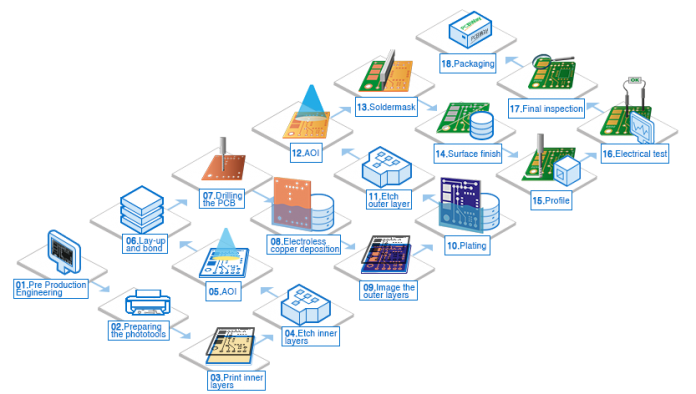
Although they’re small, the producing procedure of a PCB is pretty extensive. Whether you’re making one your self or going via a Aluminum PCB manufacturing process , a couple of steps are critical to the improvement of the board. Because every step is so important to the procedure, let’s take a near study the producing procedure of a PCB.
PCB Manufacturing Process
Step 1 – The Design
Before you start production the PCB, you want to have a layout of the board. These blueprints can be what you base the procedure off of. The layout procedure is usually finished via laptop software. Using a hint width calculator will assist with a majority of the information wished for internal and outside layers.
Step 2 – Printing the Design
A unique printer referred to as a plotted printer is used to print the layout of the PCB. It produces a movie that suggests the information and layers of the board. When published, there can be ink shades used at the inner layer of the board:
- Clear Ink to reveal the non-conductive regions; and
- Black Ink to reveal the conductive copper lines and circuits.
- The equal shades are used for the outer layers, however the that means of them is reversed.
Step 3 – Creating the Substrate
Now is whilst the PCB will begin to form. The substrate, that’s the insulating material (epoxy resin and glass fiber) that holds the additives at the structure, starts offevolved forming through passing the substances via an oven to be semicured. Copper is pre-bonded to each aspects of the layer after which etched away to reveal the layout from the broadcast films.
Step 4 – Printing the Inner Layers
The layout is outlined to a laminate, the frame of the structure. A photo-touchy movie crafted from photo-reactive chemical compounds with a purpose to harden whilst uncovered to ultraviolet mild (the withstand) covers the structure.. This will assist align the blueprints and the real print of the board. Holes are drilled into the PCB to assist with the alignment procedure.
Step 5 – Ultraviolet Light
Once aligned, the withstand and laminate pass below ultraviolet lighting fixtures to harden the photoresist. The mild well-knownshows the pathways of copper. The black ink from earlier than prevents hardening in regions with a purpose to be eliminated later on. The board is then washed in an alkaline strategy to put off the extra photoresist.
Step 6 – Removing Unwanted Copper
Now, it’s time to put off any undesirable copper that remained at the board. A chemical answer, just like the alkaline answer, eats away on the undesirable copper. The hardened photoresist stays intact.
Step 7 – Inspection
The newly-wiped clean layers will want to be inspected for alignment. The holes drilled in advance assist align the internal and outer layers. An optical punch device drills a pin via the holes to maintain the layers coated up. After the optical punch, some other device will look at the board to make certain there aren’t anyt any defects. From right here on out, you’ll now no longer be capable of accurate any overlooked errors.
Step 8 – Laminating the Layers
Now, you’ll see the board take form because the layers are fused collectively. Metal clamps preserve the layers collectively because the laminating procedure starts offevolved. A prepreg (epoxy resin) layer is going at the alignment basin. Then, a layer of substrate is going over the prepreg observed through a copper foil layer and greater prepreg resin. Lastly, there may be on greater copper layer implemented, that’s the click plate.
Step 9 – Pressing the Layers
A mechanical press is then used to press the layers collectively. Pins are punch via the layers to maintain them nicely aligned and secured, those pins may be eliminated relying at the technology. If accurate, the PCB will visit the laminating press, which applies warmth and stress to the layers. The epoxy melts inner of the prepreg that, at the side of the stress, fuses the layers collectively.
Step 10 – Drilling
Holes are drilled into the layers through a laptop-guided drill to reveal the substrate and internal panels. Any closing copper after this step is eliminated.
Step 11 – Plating
The board is now geared up to be plated. A chemical answer fuses all the layers collectively. The board is then very well wiped clean through some other collection of chemical compounds. These chemical compounds additionally coat the panel with a skinny copper layer, if you want to seep into the drilled holes.
Step 12 – Outer Layer Imaging
Next, a layer of photoresist, just like Step 3, is implemented to the out of doors layer earlier than being despatched for imaging. Ultraviolet mild hardens the photoresist. Any undesired photoresist is eliminated.
Step 13 – Plating
Just like in Step 11, the panel is plated with a skinny copper layer. After this, a skinny tin shield is layered to the board. The tin is there to guard the copper of the out of doors layer from being etched off.

